THE INFORMATION AVAILABLE ON THIS PAGE IS PROVIDED ON AN "AS IS" BASIS. THE AUTHOR MAKES NO WARRANTIES, EXPRESSED OR IMPLIED, INCLUDING, BUT NOT LIMITED TO, THOSE OF MERCHANTABILITY AND FITNESS FOR A PARTICULAR PURPOSE, WITH RESPECT TO THIS DOCUMENT AND THE INFORMATION PRESENT HEREIN. THE AUTHOR DOES NOT WARRANT, GUARANTEE OR MAKE ANY REPRESENTATIONS REGARDING THE USE OR THE RESULTS OF THE USE OF THESE DOCUMENTS OR THE INFORMATION PRESENT HERE IN. THE ENTIRE RISK OF USING THE INFORMATION PRESENT IN THIS DOCUMENT IS ASSUMED BY THE USER. IN NO EVENT WILL THE AUTHOR BE LIABLE TO ANY PARTY (i) FOR ANY DIRECT, INDIRECT, SPECIAL, PUNITIVE, INCIDENTAL OR CONSEQUENTIAL DAMAGES (INCLUDING, BUT NOT LIMITED TO, DAMAGES FOR LOSS OF BUSINESS PROFITS, BUSINESS INTERRUPTION, LOSS OF PROGRAMS OR INFORMATION, AND THE LIKE), OR ANY OTHER DAMAGES ARISING IN ANY WAY OUT OF THE AVAILABILITY, USE, RELIANCE ON, OR INABILITY TO USE THIS DOCUMENT OR THE INFORMATION PRESENT HEREIN, EVEN IF THE AUTHOR HAVE BEEN ADVISED OF THE POSSIBILITY OF SUCH DAMAGES, AND REGARDLESS OF THE FORM OF ACTION, WHETHER IN CONTRACT, TORT, OR OTHERWISE; OR (ii) FOR ANY CLAIM ATTRIBUTABLE TO ERRORS, OMISSIONS, OR OTHER INACCURACIES IN, OR DESTRUCTIVE PROPERTIES OF ANY INFORMATION.
This document originally started out as an assignment for my university course. I thought that it could be helpful to anyone interested in writing an emulator. With this in mind I have been working to refine this document to make it more readable. I have received suggestions from my lecturer and friends in this process.I will probably not have the time to make many changes in the near future, but readers should keep in mind that this document is still a work in progress.
This document covers the theory behind writing an emulator; however, it is not a step-by-step guide. I have tried to make the document as generic as possible so that the information can be applied to any machine. This will help you understand the principles behind an emulator. These principles will be able to be applied to other systems. However the information is still slanted to more recent hardware. If you were emulating older hardware issues such as timing is more crucial than I have emphasised.
Ultimately writing an emulator comes down to a lot to individual skill, understanding the target platform, and understanding the platform’s hardware. This document tries to help with the understanding of the how all this information is applied.
An emulator is a piece of software that imitates the internal design and functionality of a piece of hardware. This allows people to run software designed and programmed for a specific hardware system and to run it on a totally different system.
An emulator in some respects is similar to a simulator and the terminology is at times switched around. The way in which emulation varies from simulation is that simulation is an attempt to gain the same look and feel of the original product on a different machine than the original machine it was designed for. Simulators may be an entire new program or a port of the original source code. An emulator gains the look and feel of the original program, because it is the original program being run on the wrong hardware through the emulator.
An example of this difference is if we had a game that was designed for a console, the console being the original targeted. The developers of this game then wanted to make a version that would run on the home PC. To do this they would use part of the original source code for the console version and recreate other parts of the code to make a new version of the game. This version would have the same look and feel on the home PC as it did on the console. This is how the simulator approach works. With an emulator designed to emulate the original console on the home PC, you would run the original version thus giving the same look and feel.
Simulators for a specific program in general give better results than what is achieved by emulation. Although the difference in results between emulation and simulation can become to a point where it is not apparent to the user which method was used. The main advantage writing an emulator over a simulator is that you will be able to run lots of different programs designed for that hardware, where as a simulator will in general be a one off deal. It is an extremely difficult task, if not near an impossible in getting a program to run on a different system with out using emulation or the original source code.
Emulation has been around for a long time, other than its existences has not always been very well known. This has started to change a lot more over the past couple of years, with people starting to hear more about emulation. This is because different emulators and emulation projects are getting a lot more public attention than they have in the past. There are wide ranges of emulators that exist, for many different systems. he level of compatibility of these emulators does vary greatly as most emulators these days are still written for a hobby.
Emulators are generally written for a more powerful system than the original target hardware that they are emulating. This is because they require a lot of processing power to do the job of hardware in software. The time when the target system may not be as powerful as the original system is when you are phototyping the functionality of a new system.
Java has been portrayed as a good solution to the cross platform barrier. This is because Java is really a basic hardware system like any other computer with no special hardware and each computer having an emulator to this potential system. This is why it is possible for someone one to build a Java machine because Java is an emulation of this potential system. Some of the Java emulators offer a Java Virtual Machine. This Java Virtual Machine uses a method called JIT (just in time compilation) that re-compiles the Java code into the native code for the system. This method is also called Dynamic Re-compilation
Emulation can also been used to help create software for a system before that hardware is fully been developed. This allows the software for the new system to be tested, without the hardware being finished. This speeds up the development of a new system, because you can develop a decent amount of the software before the hardware is completed or available to test on. A good example is how Microsoft has created an emulator to help with software development for a Windows CE device. You are able to develop and test a Windows CE application on a Windows NT x86 machine with their emulator and get it running there before even touching a Windows CE device.
Emulation can also be used to help develop an operating system. Using an emulator it is a lot easier to trap different errors that occur in hardware. You are able to view information about the state of the hardware and registers when these errors occur, that you may normally not able obtain if you were using straight hardware to test. If the software you are developing cause a problem, the hardware on system can lock up and you lose all diagnosing facilities. With an emulator, the emulator is likely to tell you it has a problem trying to perform the task the program is trying to do, giving you debugging information about the problem.
There is a lot you have to know or learn when writing an emulator. Writing an emulator might be a great place to expand your programming skills, but it is a horrible place to start them. It is a good idea not to try and develop an emulator, especially the more difficult systems, as the first program you want to develop. It is best to get a decent amount of programming experience before you try to write an emulator, without a decent level of programming skills you will find progress extremely slow as your grappling with the ideas needed in emulation and those involved with learning programming at the same time.
One thing you have to realise and accept with writing an emulator is not a simple task, it is a major project that will take a large amount of time to get things working to a good level. This is true for even the basic systems.
To start an emulator you must know what system you want to emulate, you will also need to know what programming language you are going to use. Having experience with assembly is not essential, but it helps a lot. Even a basic understanding of how assembly works will be helpful. This document should help a little with getting you familiar how the system uses assembler.
The more information you have about the target system you are emulating, the better off you will be in the long run. There is a lot of information that is needed to have a highly compatible emulator. You need to get documentation about how the assembly commands are broken up and what opcodes exist on that system. This type of information can usually be found in manuals for programming the target system in assembly. This information is critical in writing the emulator and if it is not publicly available then this information will have to be reversed engineered.
Once you have a basic understanding of how the internals of the target system work and have enough programming skills you should be able to start an emulator. This document provides information to help collating all the information and skills together to help getting the first couple of steps for your new emulator.
The central processing unit (CPU) is the core of any computer. This means that when a system is emulated, the core of the emulator with be the CPU emulation. If a piece of hardware contains a CPU then we are able to emulate it. As the CPU is the backbone of an emulator you need to understand the principles of how the CPU works. The better you understand how the CPU works the easier it is to understand how to program an emulator and to solve problems unique to the CPU.
In the emulation of the CPU the aim is to input data from the system, and produce the same results as what the target system produces with this same data. This means some of the effects of the CPU can be produced with out going through the exact same method as the original system went though. If you can miss emulating parts of the system, this will generally speed up the emulation process, but you have to understand the CPU well enough to know what you can and cannot miss. Some of the things that are generally not emulated are the cache, and pipe line. With the pipeline, there are sometimes different effects that can be caused. In missing the pipeline you still have to generate these same effects as though you were emulating it.
The CPU basically retrieves information from the system, processes the data and writes back the results. These tasks are carried out by two different parts of the CPU the control unit and the arithmetic/logic unit as described below.
The control unit is responsible for directing how the processor executes the stored program instructions. The control unit does not execute the OpCodes (Operation Codes); rather it is the controller as its name suggests that direct the other parts of the system to perform the desired task. This unit retrieves the OpCode instruction data from the cache or main memory depending on the system. To humans the raw data that the control uses looks meaningless. The control unit makes sense of this data by breaking up the instruction into different parts and using an OpCode matrix and decides how to process the OpCode. What the control unit has to do with the opcode based on its parts is how we translate the raw data to assembly code, which we can easily write and program. An OpCode matrix is just a jump table to processes the broken up data quickly. The control unit then directs the rest of the hardware based off the break down of the retrieved instruction data to perform the task that is expected.
The arithmetic/logic unit (ALU) performs arithmetic tasks (addition, subtraction, multiplication and division). The ALU also performs logical operations these include comparing, binary shifts, and logic gates (OR, AND, XOR, NOT). The ALU reads the current values from the computer's registers, perform the desired operation on these values and then writes back the result to the registers.
Computers are always executing one or multiple instructions at any one time while they are running. Using a pipeline allows the computer to be able to execute multiple instructions at the same time. The way the pipeline actually works between different systems varies greatly. Some systems use the pipeline to improve the throughput of processing by executing instructions in a different or the same order than they are retrieved. This is why understanding the pipeline for optimising a program is very important.
But what does the pipeline mean to emulation? In general it does not mean much as the systems tries to make the pipeline invisible to the programmer. A program designed with the pipeline in mind will improve the speed of the program, but it behaves no differently. There are some situations where emulating a side effect of the pipeline is very important. An example of this is on a MIPS processor. A branch/jump OpCode on a MIPS processor modifies the program counter of where the instructions are fetched from, but the actual change of the program counter does not occur till after the following instruction has been started. This means that you have a delay slot instruction before the instructions are starting to be executed from the new program counter. There are some branch OpCodes that nullify this delay slot making it not execute.
The steps that are performed by the CPU in executing a single OpCode are as follows:
* Instruction Fetch - In this stage the control unit retrieves the instruction data of
the OpCode. On some systems like MIPS this is a fixed number of bytes, on other systems
like x86 the OpCode takes from 1 to 10+ bytes.
* Instruction Decode - In this stage the control unit works out what the OpCode means by
decoding it (explained below) and then directs the needed data to be moved from the
registers to the ALU and directs the ALU on what is to be done with the data.
* Execution - this is where the ALU performs the task needed to fulfil what the OpCode
expects to be done. Also any memory retrieval OpCodes read from the memory at this stage.
* Write Back - This is the last stage of processing an OpCode. In this stage the
results from the OpCode are written back to the register or memory depending on the OpCode.
The method that is used for decoding an OpCode is system dependent. The method varies between systems but all the methods that decode an OpCode take the same approach. On some systems like MIPS the data need for a single OpCode is fixed unlike an x86 processor where the instruction data need for a single OpCode is variable. The processor has to process the first fixed length part of the OpCode to work out what the OpCode is. Each part is translated using a jump table, with each going further down a tree to work out what the OpCode does and the size of the OpCode.
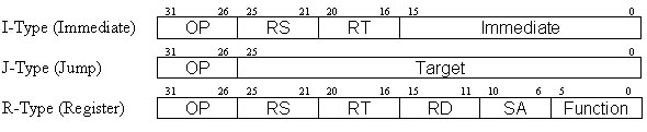
On a MIPS processor each OpCode is 4 bytes (32 bits) and is broken down using the table below. The values that appear above the OpCode types defines the start and stop bit position of each segment of information that is used by that type of OpCode. The OP field in a MIPS OpCode is the first fixed part and is used to determine what type of OpCode it is.
Here is an example of decoding a MIPS OpCode:
The Add OpCode is a Register type operation. Each part of the OpCode is broken down as shown
below. This break down comes from a MIPS processor manual. This break down has an addition
line of information below, these values tell the number of bit that are used for this field.

The way in which this OpCode is decoded is by looking at the first field, OP, which in this case is 0. This part in this case does not give us what the OpCode does, but points to another jump table (SPECIAL) that is based off the value stored in the function part of the OpCode. Now using the SPECIAL jump table and the value from the function part we are able to determine that the OpCode being processed is an ADD OpCode. This leaves 4 parts of the OpCode left that the OpCode can use. The add OpCode only uses 3 of the parts left so the last part is defined as always to 0. If this part contained another value it would not matter, as it is not used.
The MIPS add OpCode uses 3 general-purpose registers, adding the two source registers together and then storing the result in the target register. There are 32 general-purpose registers that can be addressed. The 3 parts of the OpCode that are used to address the registers are RD (destination), RS and RT (source registers). Each of these parts have a value range of 0 to 31(5 bits) which means they can be used to address any of the general-purpose registers. Although each part is separate they can contain the same value. This means that you can have the destination register the same as one or both your source registers.
There are three different methods that are used when you are programming the CPU core:
* Interpretation: In this method the emulator retrieves one OpCode from memory, translates
what the OpCode does, and then performs the desired task. This is the most basic of the 3, it
is easier to debug and get a decent level of compatibility for the amount of work. But the
down side of this method is that it is a lot slower compared to the other methods.
* Static Re-compilation: In this method the emulator grabs a block of code for the
targeted emulated system. This code is then translated into native code (ie compiled). The
size of a block is usually defined as the current OpCode to a branch/jump. This method is
similar to how a normal programming language compiler works. This is because it takes the
source code (which happens to be the native code for the target system) and then compiles it
to the native code. After it has all been compiled this compiled code is then executed.
* Dynamic Re-compilation: This method takes advantages from both interpretation and
static re-compilation but with the down side of using more system resources. In this method
you re-compile code as in static re-compilation. However of compiling everything in one go,
you compile the code that is just about to be used. When the emulator jumps to a new location
then this type of core checks to see if there has been any code at this location. If there is
then this code is executed otherwise code is generated and executed. The advantage of this
method is that you can handle some things that are impossible in static re-compilation (ie.
Self-modifying code). You are also able to use this method to work with a built in debugger
easily with similar methods to Interpretation, which is not impossible, but very complicated
to do in static re-compilation.
As the CPU is the core of a computer system, it is also the core component of an emulator. How the CPU works (as explained above) is the same general method that is applied to processing the data within the emulator. We want our program to input the same data and produce the same results even if not all steps are exactly the same. This is why it is essential to have a good understanding of the CPU so you can understand how the different steps can be changed. I am going to explain how to write an emulator using an interruptive core. It is extremely hard to go straight to go Dynamic Re-compilation or Static Re-compilation. In general these types of cores are rebuilt over an original interrupting core. The Dynamic/Static re-compilation method is beyond the scope of this document.
The basic flow of the Interrupting CPU core looks like this:
| Initialise registers | |
| While CPU is running then | |
| Load OpCode Data | |
| Translate OpCode | |
| Execute OpCode | |
| End while | |
I will explain each of these steps below and talk about some of the methods that this can be implemented in C code.
In this stage you are initialising the variables that symbolize the internal register of the target system. The values that these variables have to contain the values that the target system sets up it's own registers. There are registers that are undefined at booting, and these values will not be documented. This should not be a problem as a program should not try and to use them, but there is always a chance that a program may use them, so if a program does then you will have to set those registers to the starting value as well. Also memory should be cleared and any part that is meant to contain special values should be set here.
In some systems, there is a section of code that is uses in the booting of the system. If this code is static, then you mind find it appropriate to skip running this code. You can set up the memory and registers to make it look like you have successfully run this code instead of what it would have looked like before the code had run. You may want to do this if this is code is hidden with inside the system and you do not have a copy of the code which is run. Another reason you may not wish to run this code is you will be unable to distribute it with your emulator due to copyright laws.
This is the main program loop. The method you are using to emulate the CPU, changes how this
loop is implemented. The most common way an emulator works is where you have only one CPU and
that CPU is always running. This means that the main loop will not be exited except when you
are stopping the emulation. In this case the implemented loop would looks like this:
| for(;;) { | |
| ... Processing a single OpCode | |
| } | |
In some implementation of a CPU core, the CPU loop might need to be able to exit out of the
loop easily. This usually occurs when you are emulating a second CPU on a system and the code
for processing an OpCode are not located in the main loop (Emulation of a System that has more
than one CPU is beyond the scope of this document). For this case you would implement a loop
where you test if a variable has been changed. This variable would be set to true on starting
of the CPU, the loop would then run till the variable is set to false (or visas versa). The
reason why we use this type of loop is that we able to easily get the CPU loop to exit from
inside a different function. This method should be avoided when possible, as you gain the
extra overhead from a comparison that is performed per loop. This method would look this:
| int CPUrunning = true; | |
| while (CPUrunning) { | |
| ... Processing a single OpCode | |
| } | |
This part of the CPU emulation varies depending on the system that is being emulated. The data needed for each OpCode can be a fixed length (eg MIPS) or of a varying length (eg x86). In the case where you have a fixed length, you are able to load the all the data need for processing the OpCode at this stage. When the OpCode data is of varying length the emulator will have to read the extra data needed for the processing of that OpCode from the memory as it goes through working out what the OpCode is. Since the emulator will not know the amount of data need for each opcode before processing it, the emulator loads the minimum need data to make the first decision about what the OpCode is. I will explain more about memory management latter.
In an Interrupting CPU core there are two main methods of handling the translating of an
OpCode. The first method is to make a massive switch statement. In the case of a MIPS emulator
(the break down of the 32bit OpCode is explain in decoding an OpCode above) it would something
like this:
| switch (opcode.op) { | |
| case 0: // SPECIAL: | |
| switch (opcode.funct) { | |
| case 0: //sll | |
| case 2: //srl | |
| ... | |
| case 2: //j | |
| case 3: //jal | |
| case 4: //beq | |
| ... | |
The other method that is used in translating an OpCode is the more common approach. In this
method, the emulator sets up a table of functions for a specific field of decoding. When a case
branches to another table then this will call another function table to translate the OpCode.
The table would look like this:
| void * Opcode [64]; |
| Opcode[ 0] = SPECIAL; |
| Opcode[ 1] = REGIMM; |
| Opcode[ 2] = J; |
| Opcode[ 3] = JAL; |
| ... |
To translate the OpCode data through this function look up table look like this:
| ((void (*)())Opcode [opcode.op])(); |
The better method depends on the compiler, the switch statement can be faster if it is compiled to a jump table, but if it is compiles to a list of if else statements it is a lot slower. The Function list method is only slower compared to the jump table method because you gain the overhead of a function call per switch compared to a jump. So in general this is the better method.
Some compilers will allow you to set up labels and use a look up table of labels instead of
functions. This means that you would be calling the table like this:
| goto Opcode [opcode.op]; |
This method is the fastest, but also looks very messy, making it hard to debug, with little speed increase to warrant this method. And not all compilers will allow this method anyway.
Here we perform the task that the OpCode we have translated is meant to do. How each type of OpCode is processed is a unique process as each does something different. Most assemble manuals will contain how each OpCode works, to allow the programmer to properly make use of the different OpCodes. The flow of the OpCode should be the same as what it is in the manual. Here is some sample source code in C, showing the emulation of MIPS based OpCodes.
| void mips_special_add(void) | |
| { | |
| GPR[opcode.rd] = GPR[opcode.rs] + GPR[opcode.rt]; | |
| } | |
| void mips_special_addi(void) | |
| { | |
| GPR[opcode.rt] = GPR[opcode.rs] + (short)opcode.immediate; | |
| } | |
| void mips_special_sll(void) | |
| { | |
| GPR[opcode.rd] = GPR[opcode.rt] << opcode.sa; | |
| } | |
| void mips_special_sllv(void) | |
| { | |
| GPR[opcode.rd] = GPR[opcode.rt] << (GPR[opcode.rs] & 0x1f); | |
| } | |
This is roughly how the OpCodes are translated in to C code. opcode is a special structure that automatically separates the different parts of the OpCode based on the extension at the end. This could also be manual done with code per OpCode, or Macros could be made to do the same thing. This code does not address that some MIPS processors are 32bit and others are 64bit. This code assumes that the GPR (General Purpose Registers) are 32bit and are unsigned. These OpCodes may be correct but they still could cause potential problems. A potential problem that could occur is that these OpCodes are able to write to general-purpose register 0, which is hard coded to the value of 0. The core it self could always just reset register 0 after every OpCode saving each OpCode from having to check for it. Another potential problem with the add OpCode is that it does not check wether the operation overflow. On a real MIPS machine an overflow in add OpCode would cause an arithmetic exception. Other than things might appear correct an emulator needs to be perfect at times. The smallest little thing left out can potential stop whole programs not to work at all.